(click picture to view)
Same as above but with blank pages deleted
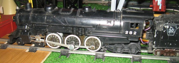
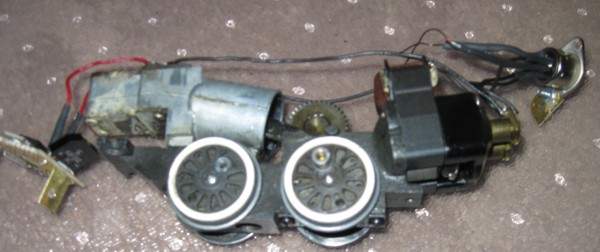
I've started to experiment with DC operation of locomotives. Here's how I converted a Steam Engine to DC:
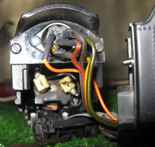
The wiring to convert to DC is pretty straight forward. (You do need to remove the existing Reverse Unit / E Unit) Essentially, the stator is provided
with DC power of a fixed polarity -- that's what the rectifier does. The rotor's polarity depends on the polarity of the track. Hence by changing the polarity of the track, one can change the direction of the train
Wiring Diagram for DC Conversion
Converting a diesel is essentially the same. The colors of the wiring is a bit different ...
Wiring Diagram for DC Conversion of a diesel
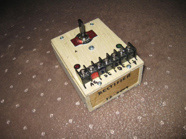
Drawing and Circuit Diagram for Rectifier with Reversing Switch
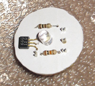
Replacing the light bulbs in the engines with LED lights is beneficial in that LEDs should never burn out, and perhaps more importantly, LEDs will not get hot and melt the plastic. For a relatively constant light output, I regulate the track voltage to 5 Volts DC and use a 100 ohm resistor with the white LEDs. Here's a diagram of what the circuit looks like.
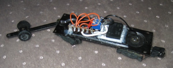
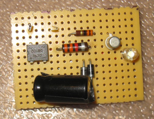
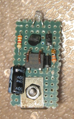
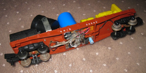
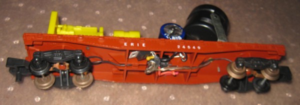
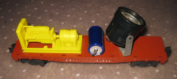
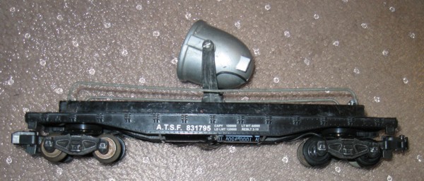
Here is how I converted a Spotlight Car to LED lighting. I used hot-melt glue to attach all the components on the underside of the flat car.
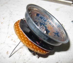
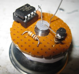
Here is an improved circuit for LED lighting. It uses a constant current source with a lower drop out voltage. The LED will maintain roughly the same brightness over the entire voltage range from an American Flyer transformer.
Constant Source LED Lighting circuit
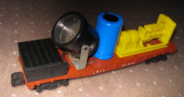
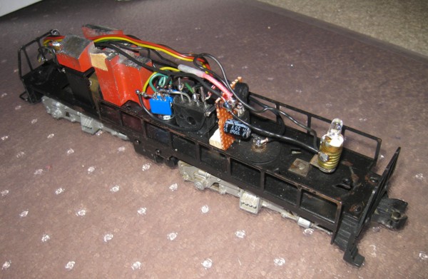
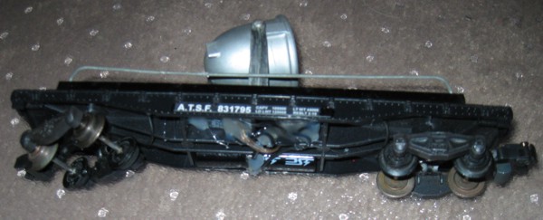
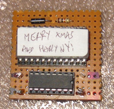
This is a neat project which has a searchlight car flash out a message in Morse Code. It probably could be done with a PIC microcontroller (Maybe a future project) but I chose this time to do it with parts that I mostly already had. The morse code message is stored in bit D0 of an EPROM (a dot uses one byte, a dash uses 3 bytes, and spaces are of various durations). At the end of the message, D7 is used to reset the 4040 binary counter. The rectifier, voltage regulator and 555 timer clock circuit are located under the flatcar. The 2716 EPROM and 4040 CMOS counter are on top under a "shed". The 15,000 uF Capacitor ensures power continuity when crossing switches and other short duration power interuptions. (I claim it looks like a fuel tank) A transistor driver and LED are located within the searchlight housing.
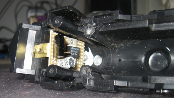
Over Christmas break in December 2011, I learned how to program and use PIC microcontrollers using the PICKIT 3 from microchip. For my first project I decided to redo the the morse code searchlight car. This version is much simpler -- I could fit the PIC and the LED driver circuit within the searchlight housing. Only the power supply had to be located under the flat car.
Circuit Diagram
Code to Program the PIC
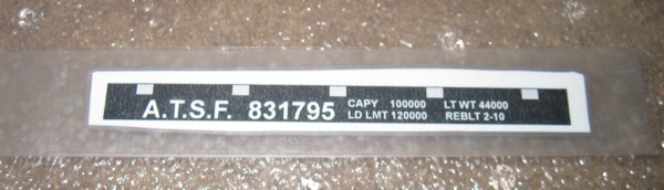
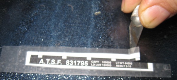
I discovered that one can make passable stickers by printing on ordinary paper on a color laser printer. Apply a strip of double side stick tape on a flat, glass surface, apply the paper, then cover with transparent tape. Trim with a knife and ruler, then carefully peel and apply.
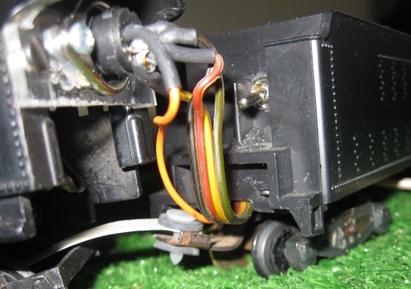
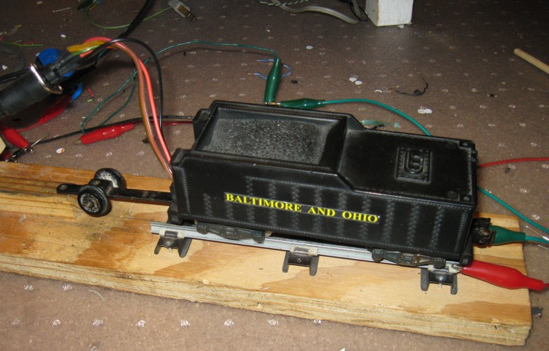
For many of my operating engines, I've used a DIN-5 Connector for the electrical connection between the tender and the engine. This allows me to swap out tenders for a given engine. I've started to create a DC tender and an AC tender for some of my engines. Note that for some engines, one has to ensure the drawbar is insulated to prevent a short. Some engines, such as the Franklin engine, use the drawbar as a conductor (in this case for the smoke unit). The DIN-5 Connector is mounted to the engine shell via a piece of plexiglass (see the document below for templates for a few different engine shell styles)
Wiring Diagram and Templates for DIN-5 Tender Connection
I normally don't operate my trains much in reverse. That said, it is nice to be able to reverse an engine to assist in recoupling cars that became decoupled, or for parking a train. The normal American Flyer e-unit that cycles between forward and reverse isn't the greatest when trying to use control systems. DC makes reversing easy, but you need a seperate transformer to make action cars work. One solution to this problem is to have the train run forward on AC power, and backwards on DC power. I've developed a number of circuits to do this, and have settled on using eitherpower FETs in an H-Bridge configuration or a 5 volt relay to change polarity, and two different sensing circuits. The first sensing circuit will have the engine move forward on AC power or DC power of one polarity. The engine will move in reverse with DC of the other polarity.
Lately I have been using the relay version for steamers because it is simpler to construct and still works reliably. Getting the relay to fit in a diesel is a bit more challenging, so I tend to use the FET based circuits for them.
The second sensing circuit is a little different in that it will reverse with DC of one polarity or with AC with a DC offset of the same polarity. Otherwise it move forward. This second circuit allows one to use a Railsounds controller to reverse the direction of the engine. Hence the engine will move forward with pure AC or DC of one polarity, and will reverse with DC of the opposite polarity or AC with a DC offset.
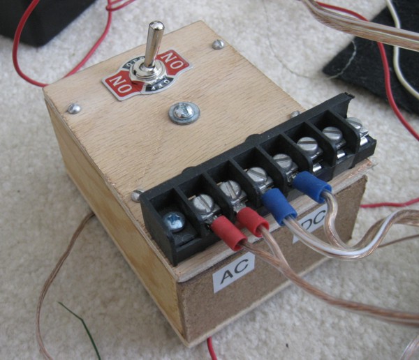
The AC-DC controller uses a half-wave bridge rectifier to produce the DC for reversing the engine. I do not suggest operating trains in reverse for extended periods of time using this particular controller because the half-wave rectifier has a very non-sinusoidal current waveform that I am sure the transformer wasn't designed for. Because the "Base Connection" connects directly to the track (only the variable voltage output switches between DC and AC), action cars will work normally.
FET based Circuit for steamers and single motor diesels
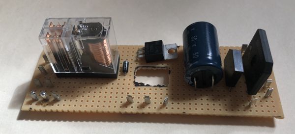
Relay version for steamers
FET based Circuit for steamers and single motor diesels adapted for use with Railsounds Controller
FET based Circuit for Can Motors and double motor diesels
Circuit for AC-DC Control Switch
Railsounds Controller
... Railsounds Controller for Reversing and Whistle
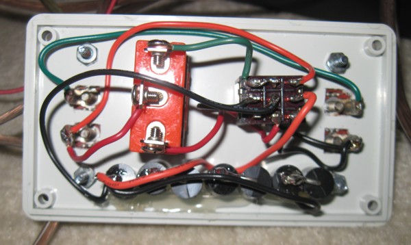
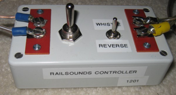
RailSounds Controller for reversing and whistle
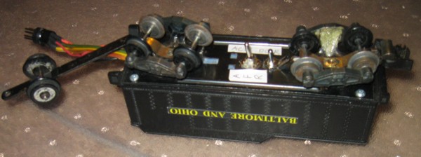
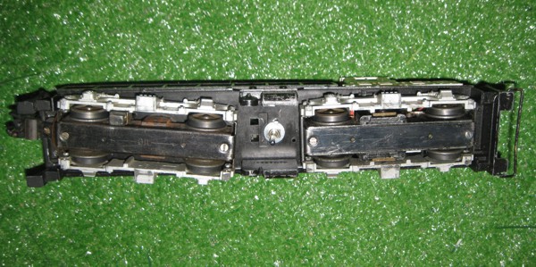
Here's a simple conversion of a Pacific to a Hudson by replacing the trailing truck. Obtained the trailing truck from LBR Enterprises . The tender for this engine includes an AC-DC reverse circuit.