
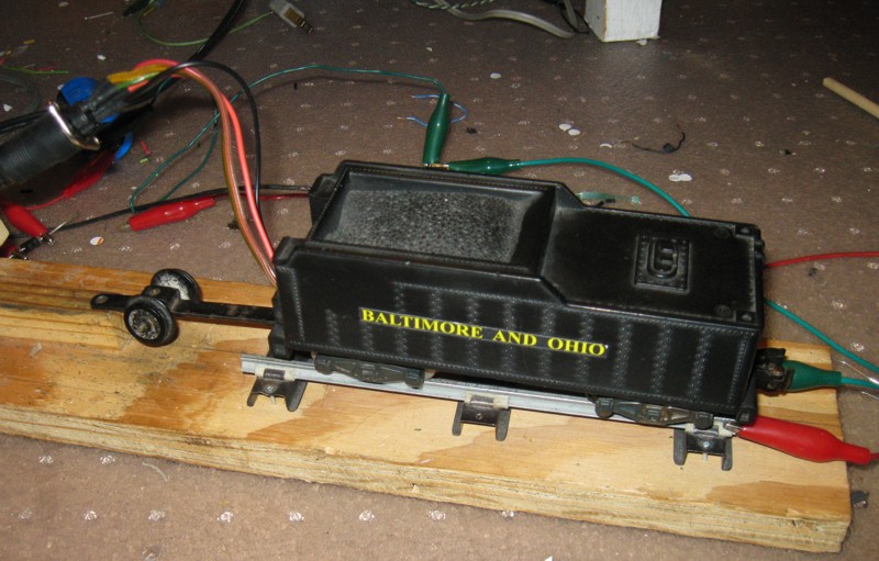
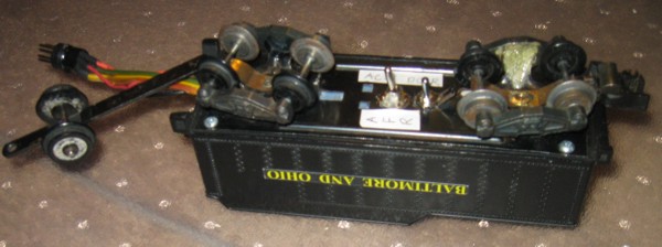
AC-DC Reversing Unit in Tender
I normally don't operate my trains much in reverse. That said, it is nice to be able to reverse an engine to assist in recoupling cars that became decoupled, or for parking a train. The normal American Flyer e-unit that cycles between forward and reverse isn't the greatest when trying to use control systems. DC makes reversing easy, but you need a seperate transformer to make action cars work. One solution to this problem is to have the train run forward on ac current, and backwards on dc current. The circuit below does this, but imperfectly. At low DC voltages, there isn't enough voltage to energize the relay, so the train still creeps forward. This means one has to quickly set the speed to some minimum ("40" on a 4B transformer) when travelling in reverse. I do not suggest operating trains in reverse for extended periods of time using this circuit because it uses a half-wave rectifier in reverse that I'm sure the transformer wasn't designed for. Because the "Base Connection" connects directly to the track (only the variable voltage output switches between DC and AC), action cars will work normally.
Circuit for AC-DC Reversing Unit
Here is an improved circuit that uses Darlington Transistors in an H-Bridge configuration to control the polarity of the field. This design works as intended. The only thing I'm still concerned about is the potential for excessive heat generation (the Darlingtons have about a 1 volt drop across them). We will see how this circuit works this coming holiday season.

Circuit for Darlington Transistor H-Bridge based AC-DC Reversing Unit
This circuit uses power Field Effect Transistors in an H-Bridge configuration. It operates much cooler than the previous circuit with the Darlington transistors. This circuit basically converts the power to DC with a rectifier, uses the H-Bridge to control the polarity, then uses another rectifier to keep the polarity on the field constant. This differs from the previous circuit in that it does not simply switch the polarity of the field. This is mainly because the field has a voltage drop across it of less than 2 volts ... I couldn't find a P-channel FET that had a Gate to Source threshold voltage low. This circuit is very useful for dual motor ALCOs where you can use dedicated rectifiers for each motor. This circuit also will work well with DC can motors


Circuit for FET H-Bridge based AC-DC Reversing Unit
Here is another FET based H-Bridge AC/DC Reverse unit. This one uses 4 N channel FETs and only changes the polarity of the field. Does not need two rectifiers and avoids the resulting 1.4 volt voltage drop. Works well for single engine diesels and steamers.

Circuit for N channel FET H-Bridge based AC-DC Reversing Unit
The following circuits modify the operation by making the engine go in reverse on only one polarity of DC. This means that the same engine will work on a DC only layout (forward on one polarity, reverse on the other polarity), will work on a purely AC only layout (forward only -- unless manually set to reverse via switch on tender), will work with the AC-DC controller (forward on AC and reverse with DC of the correct polarity). The circuit adds a DPDT switch to control which track polarity of DC voltage causes the train to go into reverse
For AC only layouts and AC-DC layouts (using the AC-DC Control Switch circuit below), action cars will work as intended since the base rail is always connected to the base on the transformer.
For DC layouts, to make action cars work, one will need a second transformer with its base terminal connected to the base rail.
Circuit for steamers and single motor diesels
Circuit for Can Motors and double motor diesels
Circuit for AC-DC Control Switch
Circuit for alternate DC detection