Serial Port Breakout Box

5 Pin DIN pin out for Train and Control Circuits
This project is used to enable a computer to control devices using my standard 5 pin DIN connector. In December 2007, I used it to interface a Commodore 64 to my Christmas Train Controls.
Manual for the Serial Port Breakout Box
Serial Port Breakout Box
5 Pin DIN pin out for Train and Control Circuits
Wire colors
Pin 1: Control A: Green
Pin 2: Control B: Red
Pin 3: Control C: Blue
Pin 4: Ground: Black
Pin 5: +12V: Yellow
Unshielded Twisted Pair (UTP) Cat 5 Wire colors
Pin 1: Control A: Green
Pin 2: Control B: Orange
Pin 3: Control C: White with Orange
Pin 4: Ground: Brown
Pin 5: +12V: Blue
Not Used: White with Green, White with Brown, White with Blue
Note: This assignment was made to be somewhat consistent with many implementations of Power over Ethernet (POE)
This project is used to display the state of several sensors in our home. The system consists of up to 7 sensors (6 currently used);sensor interface units that translate the sensor waveform to a digital signal, including the alarm singal; a Sensor Hub that collects the sensor digital signals and sends them via RS-232, a multiplex output, or a parallel output to other units; Software running on a LINUX server for remote monitorin on any workstation; and a remote indicator using the multiplex output of the Sensor Hub. The current list of sensors are:
     Flooding Alarm: Utility Room
     Flooding Alarm: Laundry Room
     Clothes Washing Machine Status (on or off)
     Clothes Dryer Status (on or off)
     Garage Door Status (open or closed)
     Mailbox Status (time since last opened)
Circuit Diagram for New Washing Machine Current Sensor (We bought a new Washing Maching machine that has very unusual current characteristics that was causing the old current sensor to not function properly)
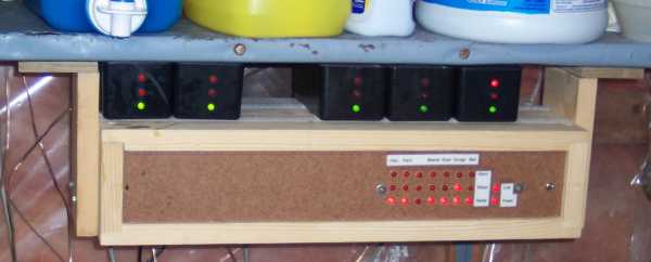
Circuit Diagram for Remote Display of Status
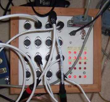
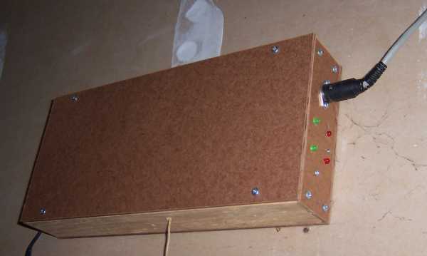
Sensor Hub with Sensor Interface Units
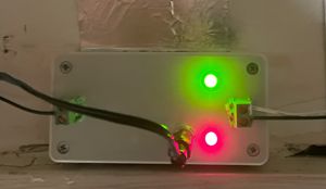
The Remote Display allows one to enable or silence an audible alarm for each sensor. It also counts (roughly) the number of hours since the mailbox has been opened (The counter resets after 8 hours or when manually reset)
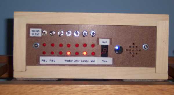
Remote Display
The Flooding Sensor interface unit measures the resistance between the two conductors of the flooding sensor. When the resistance falls below a set value, the alarm sounds. As you can see, the sensor istself is of pretty simple construction.
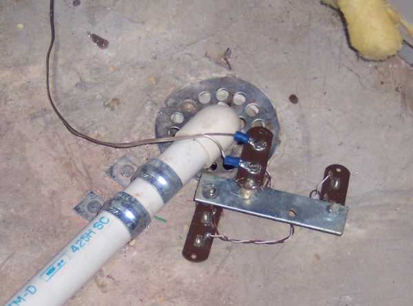
Flooding Sensor
The Garage Door Sensor (as shown) was orignally a microswitch mounted so the garage door opener will close the switch (open the circuit)
when the Garage Door is closed. Because of the relatively large motions and vibrations of the garage door opener, the microswitches
tended to become damaged. I then replaced the microswitch with a magnetic reed switch (such as used in alarm systems). It worked
much more reliably, and I used this configuration for many years. On occasion though, the magnets would not line up adequately for the reed switch
to register the door was closed.
I decided to replace the reed switch with an interface to the existing "door closed" sesnor for the garage door opener. When the door is not closed, there is about 8 volts across the sensor. When the door is closed, the sensor shorts to ground, resulting in zero volts. The interface circuit uses a darlington pair of NPN transistors to provide minimual current loading when the door is not closed. When closed, the sensor switch shorts out the base connection of the darlington pair; when open, the darlington pair turns on, and allows a current to flow through an LED of an optoisolator. The output of the optoisolater is used as the output of the interface box. This circuit does use an external source of control power. I could have tapped into the power supply of the garage door opener, but I decided not to.

Original Garage Door Sensor
Garage Door Interface unit
The Mailbox Sensor uses the circuit board from our old Stanley Garage Door Opener (circa 1985). After a little experimentation, I found a signal that corresponded to the the remote received signal. I added a connector to the board to tap this signal, and removed the various relays to reduce electricity consumption. Built an interface board to isolate the garage door opener card from the sensor interface. For the mailbox itself, I modified a remote by adding a connector to the push button, and connecting to it a magnetic reed switch. A magnet mounted on the Mailbox door activates the reed switch when the door is opened.
Mailbox Sensor Circuit
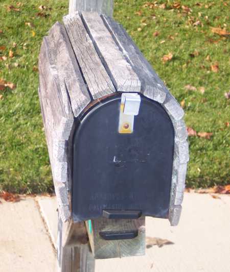
Mail Box Door Sensor (Modified Garage Door Opener underneath mailbox)
Mail Box Wireless Receiver
The Hub communicates with a LINUX based web server to generate a web page that refreshes itself to show the updated status.
Example of Web Page created by Web Server
The code for creating the Web Page is pretty basic. When I have the time, I hope to do it right ....
It does include some neat features like playing an audio file when the alarm is on.
It also can send an email (or text message) when an alarm is on
A log file can also be activiated to record the time when any sensor status changes
Source code for Web Server (Version 3.1 of Sept 2010)
So my daughter graduates from college, moves into a townhouse, and starts the working life. She mentions to me that her washing machine and clothes dryer are in the basement and it would be really nice if she could get a text when they were done. I got the hint. Of course over 13 years had gone by since I built the home monitoring system for our home -- technology has moved on. In particular, Raspberry PIs are now available and dirt cheap. I settled on using the Raspberry PI version 2 B because although it wasn't the newest, it had plenty of capabilty for what was needed and could be obtained on EBay for a very affordable price. Because the Raspberry PI has plenty of GPIO (General Purpose Input - Output) and ample computational ability, there was no need to do much of the work done in hardware with the original version. I used the pigpio library for working with GPIO. In particular, all alarms are now done in software on the Raspberry PI. The sensors provide a "low" signal on pin 1 of the 5 pin DIN connector when the sensor is activitated as well as a "Ready" signal (low) on pin 3. Pin 2 (previously used for the alarm) is reserved for future use.
The following packages where installed on the Raspberry PI (sudo apt-get install ...)
- ssmtp -- used to send emails / texts on alarms
- apache2 -- web server (make sure to 'sudo a2enmod cgi' to enable cgi scripts)
- samba samba-common-bin -- set up shares so you can modify the email messages and update the software
- telnetd -- Enables remotely logging into the Raspberry PI so you don't have to open the box
I copied sensor.exe and sensor_client.exe to /usr/lib/cgi-bin
I copied the alarm exectuables, email files, audo files and sensor_logging_on.txt to /var/www/html/sensor
I edited /etc/rc.local to include
sudo /usr/lib/cgi-bin/sensor.exe &
While sensor.exe does the heavy lifting, a web-page communicates with it via sensor_client.exe. Essentially one creates an html link to [server]/cgi-bin/sensor_client.exe. Where [server] is the name of the Raspberry PI or its IP address. (some browsers can't figure out the IP address of a local server).
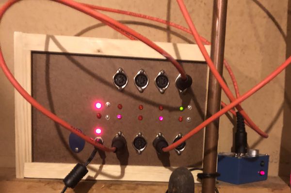
The design of the board was done in a modular way with spare area to facilitate future revision. The basic design is the same as the Light Timer (see below) but with a different configuration of ports. The Raspberry PI is powered with 5V DC provided via the 40 pin connector. Note that it bypasses the circuit protection on the Raspberry PI, but I thought this was acceptable since the 5V supply is contained within the enclosure. The 5V supply is produced with a 7805 linear voltage regulator. To reduce the power dissipation in this regulator, its input is connected to a 12V supply via a 7.5 ohm 10 watt resistor. The regulator still gets hot, so a heat sink is recommended. The 1000 uF capacitor holds up the input voltage to the 7805 regulator during current surges. (In hindsight, I should of used a 12V to 5V switchiing converter -- although cascading multiple power converters can cause stability issues which may require an input filter to the converter)
The ten LEDs are all individually controlled via dedicated GPIO pins. For the LEDs near each 5 pin DIN connector, the intensity of the LED is programmed to reflect the combined inputs of Pins 1 and 3:
A pin is "on" if shorted to ground; A pin is "off" if it has a high resistance to ground
If Pin 1 is "off" and Pin 3 is "off" the LED is off
If Pin 1 is "off" and Pin 3 is "on" The LED is very dim
If Pin 1 is "on" and Pin 3 is "on" the LED is bright
The remaining condition is an abnormal condition (Pin 1 is "on" and Pin 3 is "off"): The LED is moderate
The top two LEDs flash alternately with a period of about 2 seconds. This is inteded to indicate the controller is not frozen and still operating. During statup, both LEDs will be dim because the GPIO ports used (2 and 3) have internal pull up resistors (~1.8K) that cannot be turned off.
This monitoring system was built with expansion in mind. Only 3 of the 7 input ports are currently used. For most sensors, the only file that need be modified is sensor_init.c. The function init_sensor(SENSOR *s) should be modified to add the details for the new sensor:
case 4: // the case is the 5 pin DIN connector number (port number) for the sensor
ss->sd->name = copystr("Not Used"); // give the sensor a name
ss->sd->sensor_enable = 0; // set to 1 to enable
ss->sd->gpio_status = 15; // don't change: GPIO for pin 1 of the 5 pin DIN connector
ss->sd->gpio_ready = 23; // don't change: GPIO for pin 3 of the 5 pin DIN connector
ss->sd->gpio_led = 7; // don't change: GPIO for the LED next to the 5 pin DIN connector
ss->sd->debounce_ready = 1; // time in seconds the ready signal has to be different before the
change is recognized
ss->sd->debounce_status = 1; // time in seconds the status signal has to be different ....
ss->sd->delay_0_to_1_status = 1; // Amount of time the debounced signal is off before considred off
ss->sd->delay_1_to_0_status = 1; // Amount of time the debounded signal is on before considered on
ss->sd->time_alarm_on = 5; // number of seconds the alarm is on after the status changes from on to off
//if set to 0, is on as long as status is on
ss->sd->status0 = copystr("On"); // Use a different label if appropriate
ss->sd->status1 = copystr("Off"); // Use a different label if appropriate
ss->sd->color_status0 = copystr("red"); // Use a different color if appropriate
ss->sd->color_status1 = copystr("green"); // Use a different color if appropriate
ss->sd->alarmfile = (char *) NULL; // filename of audio file to play when alarm is on /
ss->sd->alarm_command_filename_with_path = (char *) NULL; // filename of system command when alarm is on
break;
Once the changes are made, rebuild the executable with make -k. Move the executable to the proper directory and ensure the permissions are correct. (sudo chmod 755 sensor.exe)
Future Improvements:
a. The saving and reading of a file to preserve the times of last status change when shut down and re-energized does not appear to be working entirely correctly
b. the path for audio file for the alarm may not be correct
c. should add an indicator for when alarm should sound: leading edge, trailing edge, on, off, or not-enabled.
d. use a configuration file for sensor details instead of hard coding.
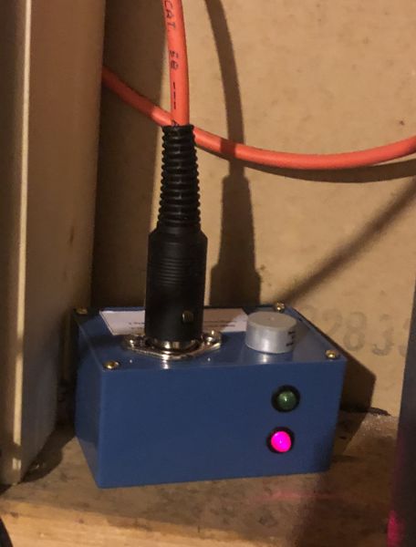
Washer Sensor
The washer sensor uses a current transformer (CT) to detect a.c. current on the black "hot" wire of the power cord going to the washing machine. The resistor and capacitor between the CT and the rectifier are chosen to match the characteristics of the washing machine and the CT. In hindsight, because these components can change if the current transformer or washing machine changes, the resistor and optional capacitor should be part of a separate module or board, distinct from the remainder of the circuit. (see dryer sensor below). The resistor should be low enough so that the maximum current does not result in an "unsafe" voltage (i.e. greater than about 40 volts). It should be high enough so that if someone attaches a voltage source to the input, it doesn't burn up the rectifier or diode. Since these components should be rated for above 1 amp, a resistance of at least 12 ohms should be chosen if the maximum voltage available for someone to misuse is 12V. A resettable fuse may be useful here instad of a resistor. The capacitor is optional, but can be used to filter out high frequency "noise" that may cause false positives.
When the washer is off, the input OP-AMP is biased so that the negative input is greater than the posiitve input, hence resulting in the output pegging at the low voltage. If the current through the bridge rectifier (from the current sensor) is greater than about 1/8 milliamp, the bias current is overcome and the positive input to the OP-AMP becomes more positive than the negative input, resulting in the ouput pegging at the positive voltage. The diode across the OP-AMP input pins keeps the differential voltage to a manageable value. With an a.c. current from the current sensor, the output of the first OP-AMP will be a series of pulses every 8.3 ms. An aysmetrical filter is used to convert this pulse into a d.c. value. On a low to high transition, the 1 uF capacitor charges predominately through the diode and 1K resistor with a 1 millisecond time constant. Hence the output of the first OP-AMP need only be on for a short portion of the 8.3 ms for the capacitor to be charged. On the high to low transition, the discharge is governed by the 22K resistor with a 22 ms time constant. This means the voltage on the 1 uF capacitor will not decay much between the 8.3 ms pulses when current is detected. The second OP-AMP is a level detector and is used to convet the voltage on the 1 uF capacitor into a solid high or low output. The output of the second OP-AMP drives an NPN transistor through a resistor and LED. Because the low value of an OP-AMP can be several volts above ground, the voltage drop across the LED and base-emitter junction of the NPN transistor are important to ensure the transistor is actually off when the output of the 2nd OP-AMP is low. Without the approximately 2 volt drop of the LED, the NPN transistor would probably still be "on" with the output of the 2nd OP-AMP low. Note that while the circuit diagram shows the use of 741 OP-AMPs, I actually used TL061 OP-AMPs because I had a bunch of them on hand.
I did consider providing hysteresis via positive feedback on the 2nd OP-AMP (add ~150K resistor from output to positive input) but determined that the asymetrical filter should work fine. Experiments confirmed this conclusion.
The signal on Pin 3 is generated by biasing an NPN transistor into saturation. Hence the low resistance of pin 3 to ground indicates to the sensor controller that this sensor is connected and has power.
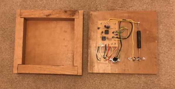
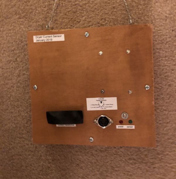
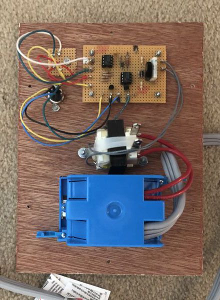
Dryer Sensor
The dryer sensor is essentially the same as the washer sensor. Because the dryer is 220 volts, the CT is located on one of the input leads to the dryer. The CT interface circuit is a separate board from the rest of the circuit. I also increased the discharge resistance from 22K to 33K, to increase the decay time to roughly 3 times the pulse period.
For this circuit, I am using a Watlow 16-0246 Current Transformer which is rated for 50 amps (50 ma from coil). With the circuit, should be able to detect currents on the order of an amp. I also noticed that on an older dryer, while the heating coil is connected line-to-line on the 220 volt circuit, the dryer motor is connected from line to neutral. This means that it may matter which of the two "hot" wires the current transformer senses. If the circuit periodically turns off while the dryer drum motor is on, try switching the current transformer to the other "hot" wire.
Flooding Sensor
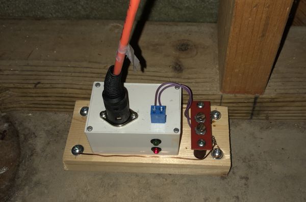
The flooding sensor detects resistance across its sensor terminals. If the resistance drops below about 1.7 mega-ohms, the PNP transistor turns on, which then turns on an NPN transistor with its collector connected to pin 1. The sensor is essentially pairs of conductors (connected in parallel) positioned so that a continuous path of water exists between the two conductors of each pair when flooding is occuring (and not otherwise). I mounted the box containing the circuit on a block of wood with bolts for "legs" that also served as the sensor inputs. A screw terminal was included to enable the addition of other sensor inputs.
The alarm is very simple: a 12 Volt buzzer connected between the 12 V supply and pin 1. Indicator LEDs are included and a reverse biased diode across the buzzer in case the buzzer used has any inductance.
A future project may be to develop a wireless alarm.
Software for sending commands from the command line
Our house is a traditional two story colonial which is very common here in Northern Virginia. In the front side of our house, we have 5 windows in 3 rooms on the 2nd floor and 4 windows in 3 rooms on the 1st floor (with the front door in the middle). During the Christmas holiday season we have small electric candles in the windows. For a number of years I used X-10 controllers to coordinate turning these lights on and off. Unfortunately, several years ago, the legacy computer running the software died and the software would not run on Windows 10. Had to resort to using traditional timers on the lights. Now the timers aren't bad, but trying to keep them even somewhat coordinated is a challenge. Hence the desire to throw technology at this minor annoyance.
While there are WIFI controlled outlets / controllers and other home automation solutions available on the market, I decided not to use these because these controllers all use proprietary formats and I feared in a couple of years the hardware running the software would go obsolete and I wouldn't be able to use the controllers anymore. The X-10 obsolescence issue would happen again. Hence I decided to "make" instead of "buy."
The original plan was to create four controllers; two for each floor. Two rooms on each floor could share controllers. This would require one new cable run to link two rooms on the first floor (which would be relatively easy to do since the runs could go through the basement). These controllers would feature:
1. connect to my home network via WIFI
2. use UDP broadcast so I didn't have to worry about IP addresses or recognizing hostnames.
3. use a command line program on a controlling PC (or Raspberry PI) and use Task Scheduler (or Cron) to send commands to turn the lights on and off.
4. use a hash for authentication of messages (a nice to have to learn about hashes)
During the development of the software, I had difficulty getting the UDP packets to be delivered over WIFI. Only about 10% of the packets were getting through. With a wired ethernet connection all made it through. With TCP over WIFI, all went though. Likely a router configuration problem, but I couldn't figure it out.
Time for plan B: Use a wired ethernet connection and save the WIFI problem for another day. This meant I had to replan where I was going to locate my controllers. Since I would need to run additonal cables anyway, I could also reduce the number of controllers to 2: one for each floor. Each controller would communicate with a cable to three 120 volt controlled switches; one for each room on each floor.
This was my first project to learn about GPIO on the Raspberry PI. While the hardware is very similar to the "New Improved Model" of the sensor system described above, the software is very different. Three different programs were written and can be downloaded using the links above:
1. nhdctrl.exe TO_NAME -- this program accepts UDP commands designated to TO_NAME and turns the appropriate output port on and off
2. nhdtimer.exe -- this program uses a configuration file to turn lights on and off at specific times
3. nhdctrlcmd.exe -- This is a command line program for manually turning lights on and off
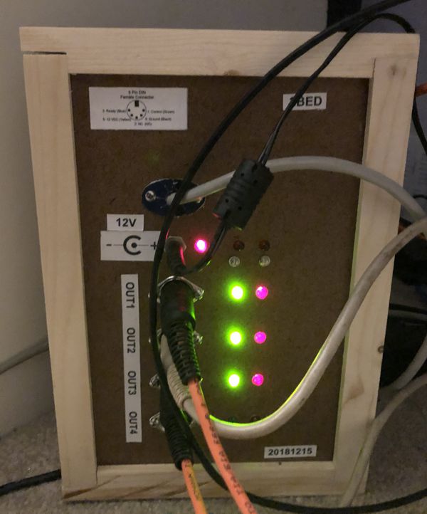
Next to each port on the hardware controller is a green LED and a red LED. The red LED is on when a device is detected. The green LED is on when the port is commanded to turn on. The top two red LEDs on the right are not currently used.
As indicated above, the original plan was to use nhdctrlcmd.exe with Task Scheduler (on a Windows Machine) or Cron (on another Raspberry PI). When I had difficulties getting UDP packets to go through via WIFI, I wrote nhdtimer.exe which resent commands periodically (every few seconds initially, then every 5 minutes). I ran this program on a Raspberry PI I had initially intended for the 3rd controller. Even though I switched to using a wired ethernet connection, I decided to keep using nhdtimer.exe. nhdctrlcmd.exe is still useful for testing the controllers.
The message protocal is:
nhdctrl command FROM_NAME-TO_NAME-DEVICE-COMMAND TIME-TICKS-AUTH
where
FROM_NAME is the name of the master sending the command
TO_NAME is the recipient (remote device receiving the command)
DEVICE is the name of the device on TO_NAME for now {OUT1, OUT2, OUT3 ... or global}
COMMAND is the name of the command
TIME is the time stamp for this command in hexadecimal (time() 8 characters)
TICKS is the output of clock() in hexadecimal 8 characters
AUTH is an authorization code (intended to prevent spoofing) 4 characters
If the command is found to be authentic, it is implemented
Once the command has been implemented, the recipent sends ...
nhdctrl [completion_code] FROM_NAME-TO_NAME-DEVICE-COMMAND STATE TIME-TICKS-AUTH
TO_NAME, FROM_NAME, DEVICE, COMMAND, TIME-TICKS are the same as the original command
completion code from
{
done = command implemented
ERR1 = error, device not supported
ERR2 = error, device error (lost comms with device for example)
ERR3 = error, command not supported
ERR4 = error, unspecified
}
STATE for outputs, provides code that indicates which state the device is in
{
0 = off
1 = on
2 = unknown
3 = undefined
}
For controlled switches,
CMD can be
{
ON (sets output to ON, then returns state in STATE)
OFF (sets output 1o OFF, then returns state in STATE)
PING (does not change output, then returns state in STATE)
SHUTDOWN (shutdown the server process) (device global only)
REBOOT (reboot the machine) (device global only)
DELETE_LOG (deletes the log) (device global only)
}
The following packages where installed on the controllers (sudo apt-get install ...)
- samba samba-common-bin -- set up shares so you can update the software
- telnetd -- Enables remotely logging into the Raspberry PI so you don't have to open the box
I copied nhdctrl.exe to /home/pi
I edited /etc/rc.local to include
sudo /home/pi/nhdtrcl.exe TO_NAME &
Where TO_NAME is the specific name of the controller (I used 1BAT and 2BED for my two controllers)
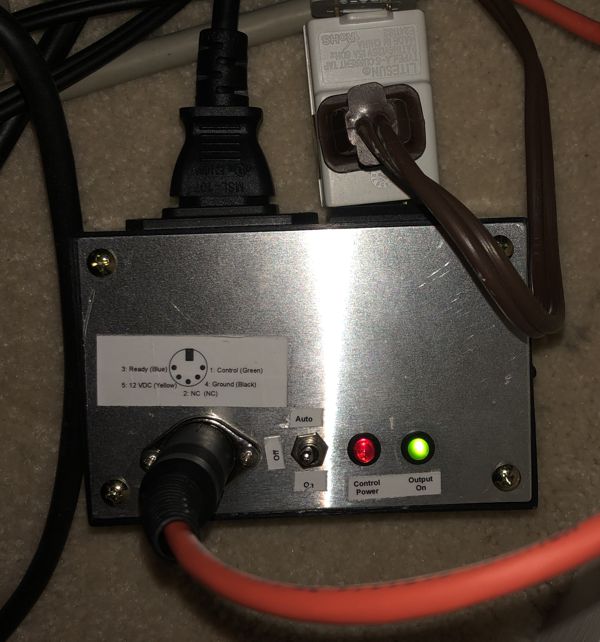
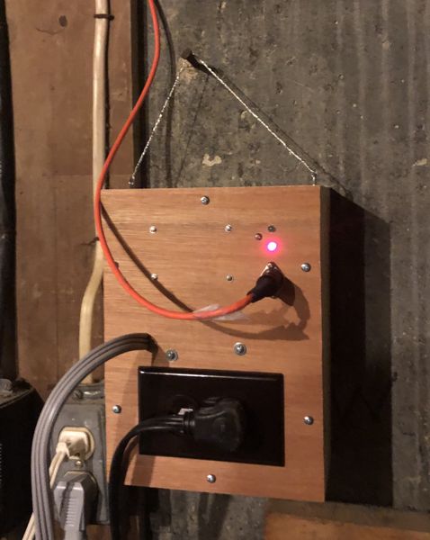
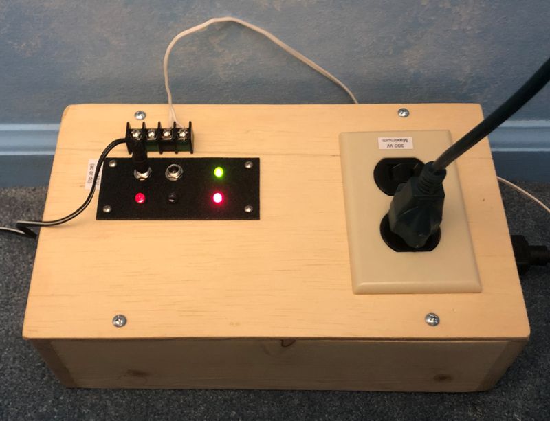
This is a real simple circuit that uses a PNP transistor to turn a relay on or off. The relay controls power to a 120V a.c. outlet. Nothing special here.
The center off switch is used to manually turn the outlet on or off, or in the AUTO mode, have pin 1 of the 5 pin DIN connector control power to the outlet (low resistance between pins 1 and 4 will turn the outlet on). Control power (12V) from the 5 pin DIN connector must be present to turn the outlet on. The red LED indicates if control power is present. The green LED indicates if the outlet is turned on.
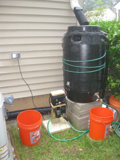
This project is used to automatically turn a pump off when the water in a rain barrel reaches the low water point. It works by measuring the resistance of the water between two stainless steel bolts. The circuit uses positive feedback to implement a hysteresis so that the pump doesn't cycle on and off near the low water mark. When the pump is not being used, a bucket is inverted over the controller and pump to keep them dry during rain.
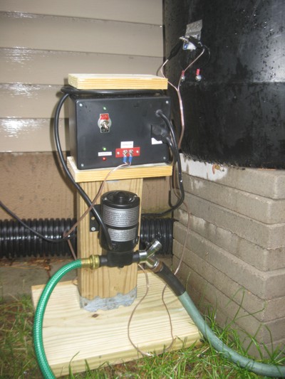
Circuit
Directions for Operation
This project allows two control inputs to turn a 120V light on or off. The light is on only if one of the two inputs are on (Exclusive Or - XOR).
The control inputs can either be a low voltage on - off switch, or a voltage between 4.5 and 18 volts (either a.c. or d.c.).
I made this project for our guest bedroom where the normal wall switch turns on/off an a.c. wall power adapater / transformer (9 V a.c.) and another
switch is mounted on the headboard of the bed. This allows guests to turn on the lights when entering the room, then turn them off when
they are in bed. (or turn them on in bed, and turn them off when leaving the room). An a.c. wall power adapter is preferred over a d.c.
wall adapter because the filter capacitor in the d.c. wall adapter will take a few seconds to discharge after power to the adapter is turned off.
Here's a version of the circuit that I built in 1993 (It still works) ..... Circuit