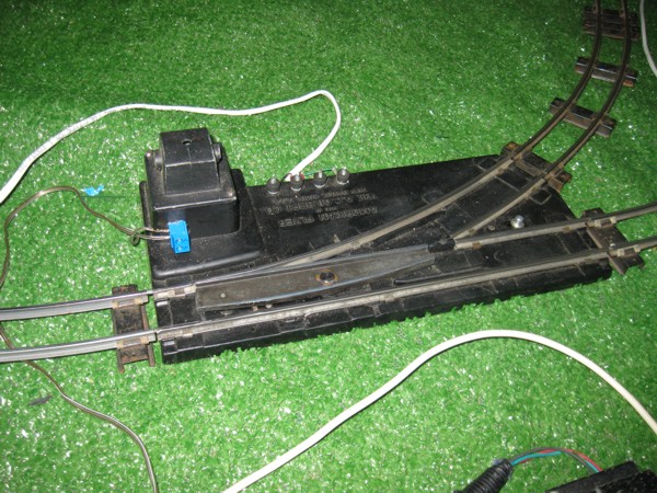
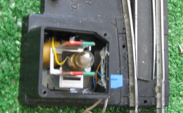
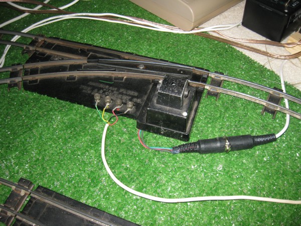
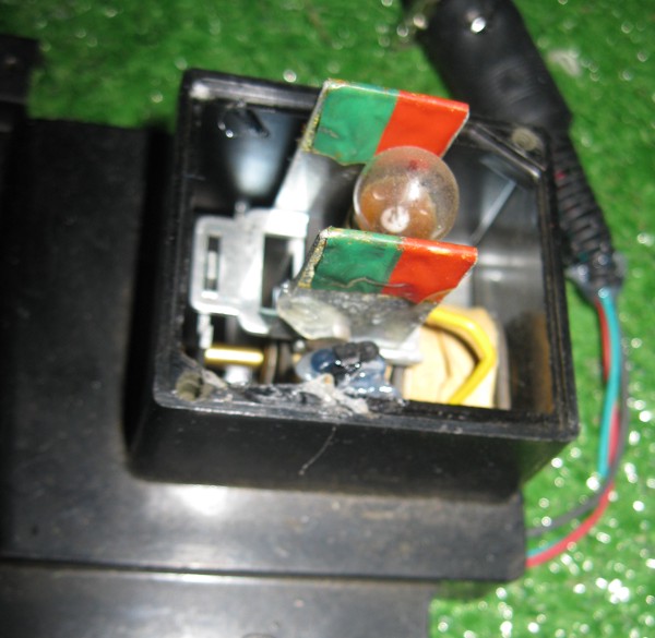
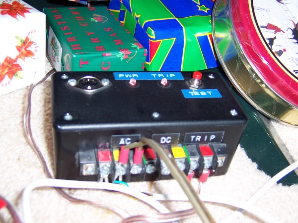
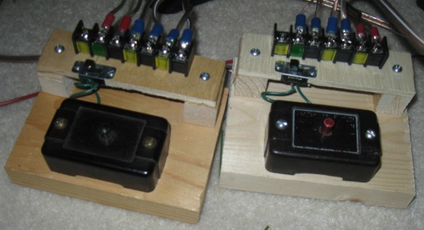
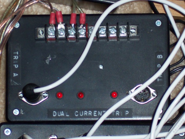
Current Trips sense if the train engine is drawing current from a block of track. I've built two different types of current trips. The first is purely electronic in that it uses a transformer and electronic circuits for the sensing. The second is an emulation of the American Flyer #26722 Electric Track Trip and is purely eltro-mechanical with a solenoid and a microswitch. In use, this one has a bit of a voltage drop that results in the train engine slowing while in the control block
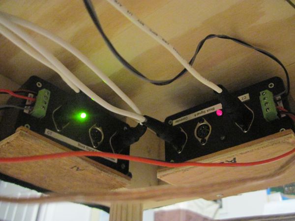
Dual Electronic Current Trip
Electric Track Trip
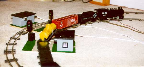
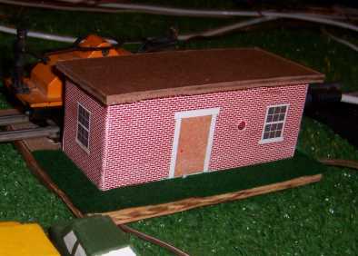
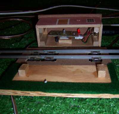
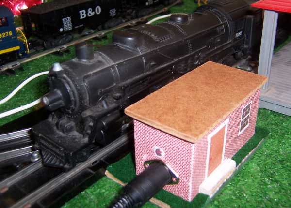
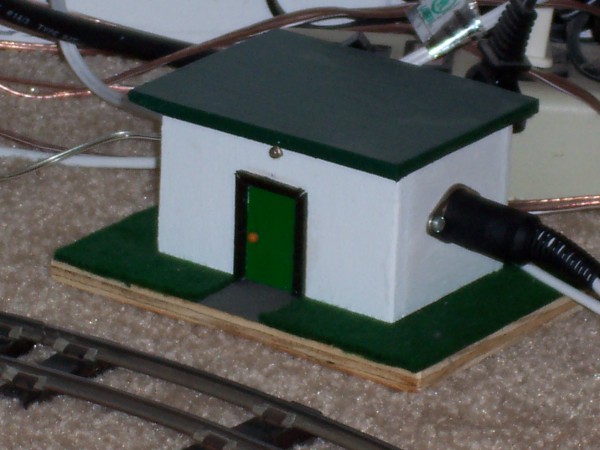
I'm also using IR Track Trips made by TCH Technology. These trips are designed to be installed under the track, but since my layout is built directly on the floor, I had to construct buildings to house the trips.
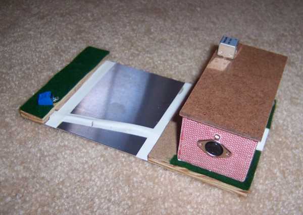
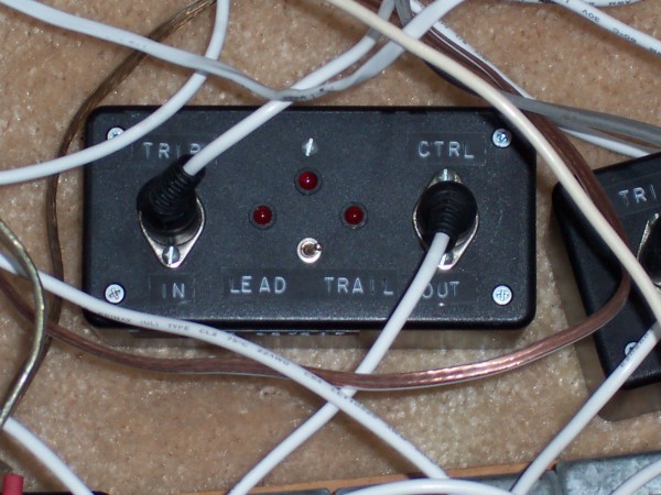
Here's an exit trip implementation (located at the exit switch) using the Sensa-Trak II tm built in December 2007. This trip included an interface board.
In general, the reflective IR trips work well if sunlight isn't filling the room. Had problems during the day time with trying to keep the sensors from being saturated. At night, all worked well.
The following is another exit trip implementation using a beam interruption circuit. I tried using a Radio Shack 276-640 IR Receiver Module, but couldn't get it working reliably. (Need to do some more experimentation). Went back to using my last IRM 8420 module.
The previous IR-Track Trips worked well on my floor Christmas Layouts, but they took up too much room on my permanent layout. Hence some minor changes were needed ....
2. End of Train Processor
End of Train Processor
One of the problems with most track trips is that while they are good for detecting
when the train arrives, they aren't that good for signalling when the train has
departed. This circuit generates a pulse when the train has successfully passed a
track trip.
End of Train Processor Circuit
3. 696 Track Trip Conditioner
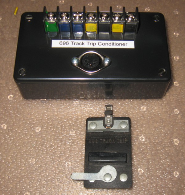
AF 696 Track Trip Conditioner
The American Flyer 696 track trip provides a connection to one of the train rails when
the wheels of a car or engine presses down on a shoe and forces two contacts together.
This is great for controlling accessories that need A.C. power, but not so great if
you are using D.C. control circuits. This circuit uses a relay to isolate D.C. control circuits from the A.C. of the 696 trip.
AF 696 Track Trip Conditioner Circuit
Alternate AF 696 Track Trip Conditioner
This alternate circuit allows you to connect to either rail of the track and uses optoisolaters to isolate D.C. control circuits from the A.C. of the 696 trip.
Alternate Track Trip Conditioner circuit
4. Block Inhibit Signal
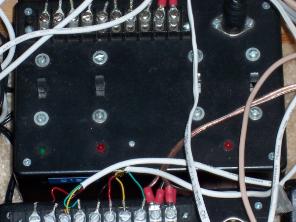
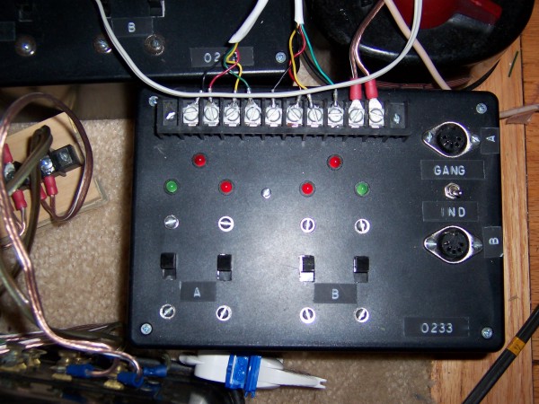
The following circuit is used to generate a Block Inhibit signal to the controller based on either a switch direction sensor, or a manual input. For the switch Direction Sensor, I modified a remote control switch by adding a small reed switch and gluing a magnet to the light "shutter." The reed switch closes when the switch is in the curved condition. The following circuit enables one to invert this signal (low value when the switch is in the straight direction) or apply a signal manually.
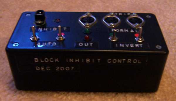
Switch Direction - Block Inhibit Signal Control Box
Switch Direction - Block Inhibit Signal Control Box Circuit
5. Remote Switch Controller
5.1 Relay Based
Remote Switch Controller - Dec 2003
Improved Switch Controller - Dec 2003
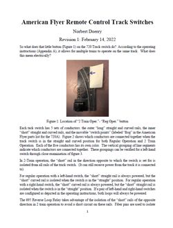
I built my own switch controllers because I needed ones that would enable me to either control the switches manually (local control) or enable the control system to automatically set the switches (automatic control). The circuits I developed also add a safety feature that prevents the control system from burning out the switch by energizing both coils at the same time.
Switch Controller
Improved Switch Controller
5.2 Power FET based
The following Remote Switch Controller is entirely solid state using Power FETs. Its also somewhat less expensive than using relays.
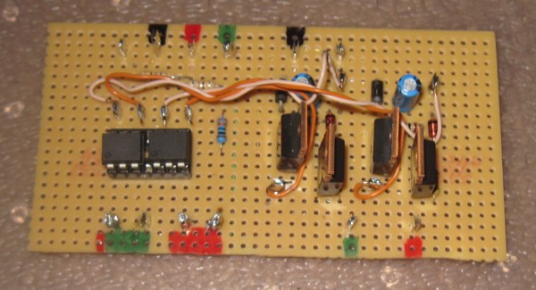
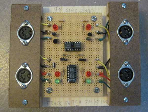
Solid State Switch Controller Board - January 2015
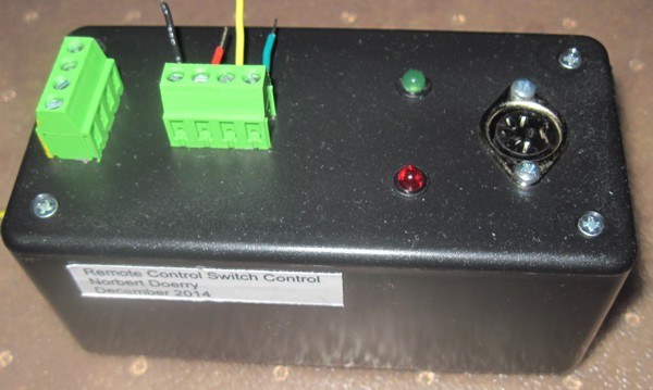
Solid State Switch Controller - January 2015
This controller is intended to be controlled entirely by an Arduino; the controller does not have a local control capability. A remote switch coil is energized by grounding the appropriate input. Note that if both inputs are grounded, neither remote switch coil is energized. Two sets of terminals
for the AC accessory power (on the 4 pin terminal on the end) enable daisy chaining of multiple switch controllers
Solid State Switch Controller
5.3 Switch Emulator
Switch Emulator - June 2015
The following circuit is used to emulate a switch and its direction detection for use in developing automatic controls. When trying to debug software on an Arduino or other controller, its more convienent to not have to use the actual hardware. This circuit can emulate two switches. The "coil" inputs are defined in the same manner as in the controllers described in 5.1 and 5.2. The "switch direction" outputs are defined in the same manner as the switch direction detection circuits in section 6.
Schematic and Drawings for Switch Emulator
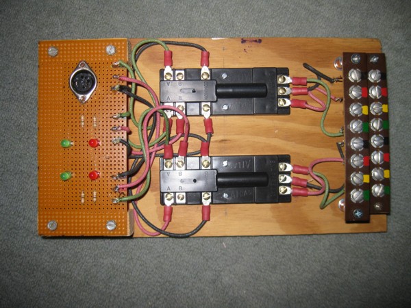
5.4 American Flyer Remote Control Track Switches - Electrical Properties.
If you wondered what that little button on the 720 track switch labeled "2 Train Oper." - "reg Oper." does, the following short document is for you.
6. Switch Direction Detection
The following controllers are designed for manual throwing, but provide feedback to the control system as to the direction the switch was thrown. The first example taps into the lights of a normal American Flyer switch controller and provides an optically isolated digital signal. It will fail if the controller lights are not on, or if the switches are manually thrown. The second uses Atlas Snap Switches to do the same thing. The atlas snap switches are hooked in parallel with the switch machines and change state the same time that the switches are remotely operated
6.1 Modified Switch Controller
Opto-isolated switch position indicator
Schematic and Drawings for Opto-Isolated Remote Switch Position Indicator
6.2 Atlas Snap Switch based switch Direction Detection
Atlas Snap Switch switch position indicator
Drawing of Atlas Snap Switch position indicator
6.3 Modifed Switch
The following shows what I'm currently using, which are modified switches. In my first version, I used a magnetic reed switch and a strong rare-earth magnet. I used hot-melt glue to glue the magnet to the shutter carriage and the reed switch to the casing. One mistake I made was to put the connector on the inside of the switch. This connector is an obstruction for long passenger cars on the curved section of track.
Rev A modified switch with magnetic reed switch position sensor
Internals of Rev A modified switch with magnetic reed switch position sensor
In my second version, I used a hall-effect sensor (Cherry Corporation MP101301, Jameco 513244), and used a DIN connector. Like before used a strong rare-earth magnet (From Radio Shack) hot-melt glued tothe shutter carriage and the sensor hot-melt glued to the case. There are many other hall-efffect sensors on the market -- Jameco no longer carries the MP101301. A common one is the type 3144.
Rev B modified switch with a hall-effect sensor to sense direction
Internals of Rev B modified switch showing hall effect sensor and magnet
Both versions of the modified switches work from a sensor perspective. On some of my switches, the magnetic reed switch proved somewhat unreliaable and I subsequently replaced them with Hall Effect sensors. I still have several magnetic reed switches on my layout that are reliable ... not sure why some proved more reliable than others. All my Hall Effect sensors have been reliable.
If a connector is used, it should not be installed on the track side of the control box because of potential interference with train cars. The pigtail (with appropriate strain relief) used with Rev B seems to work well.
Directly sensing of the switch position within the switch itself improves system reliability by preventing problems when someone manually changes the direction of the switch.
7. Block Controller
7.1 Single Block Controller
Block Controllers
The Block Controller enables control logic to switch the source of power (or turn power on or off) for a block of track. It also can emulate the American Flyer Lockout Elminator which stops a train without causing the reversing unit to activate and start the engine in reverse after power is re-applied to the block.
Block Controller Circuit
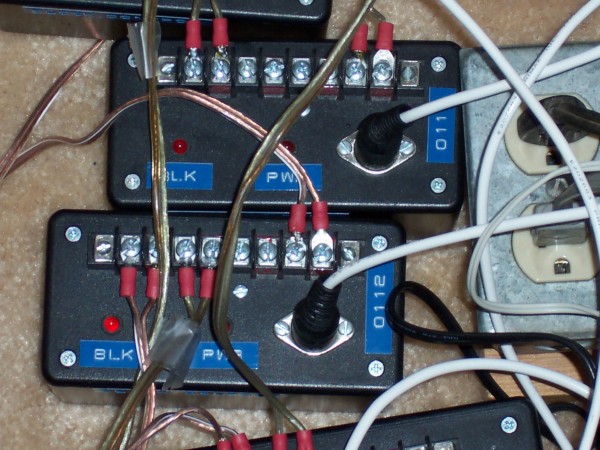
7.2 Dual Block Controller
Here's a modified block controller used as a dual block inhibit for the two entry blocks
Dual Block Inhibit Controllers - December 2007
Dual Block Inhibit Controller Circuit
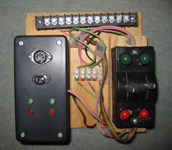
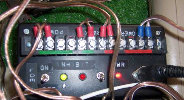
7.3 Shared Block Controller
Here's a shared block controller to control which transformer will control the shared block
Shared Block Controller - December 2007
Shared Block Controller Circuit
8. Master Controller
8.1 Relay Controller
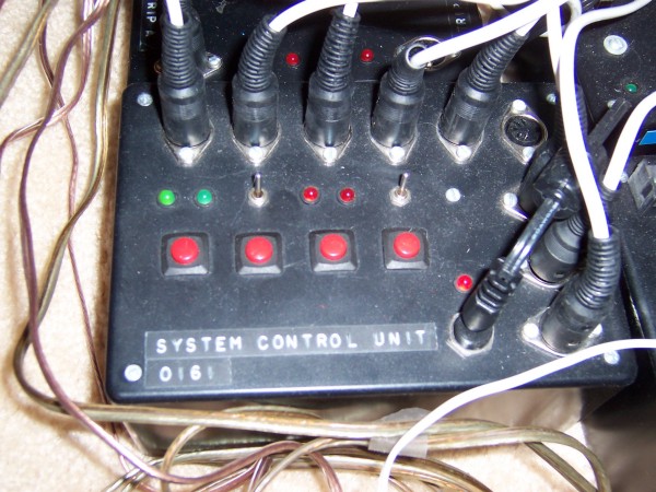
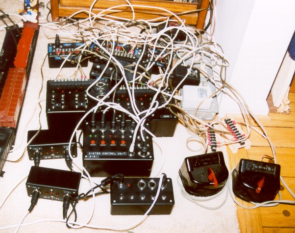
Master controller in December 2003
The Master Controller determines which train should have control of the shared block, and generates the proper signals for the Block Controllers, the Remote Switch Controller, and the Block Signal. The circuit is a combination of Relay Logic and signal conditioning. In 2007 I replaced this control box with a microprocessor based (Commodore 64) controller.
Master Controller Circuit
8.2 Commodore 64 Based Controller
The Serial Port Break-out box enables a computer (such as a Commodore 64) to send 8 bits of output control signals and receive 8 bits of control signal inputs. The code was written in assembly language, assembled using my own CA cross-assembler (Dowload CA cross-assembler here) and burned into an EPROM. Bought several Game Cartridge boards with sockets off of EBay to hold the EPROMs.
Commodore 64 Train Control Assembly Language Code and Binary
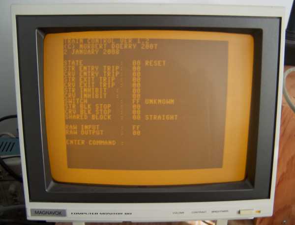
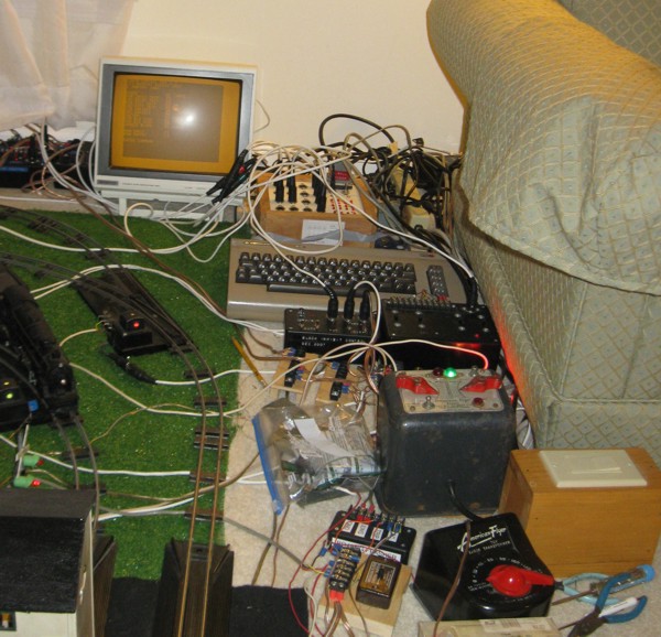
Commodore 64 Train Control Screen Shot (on Monochrome Monitor)
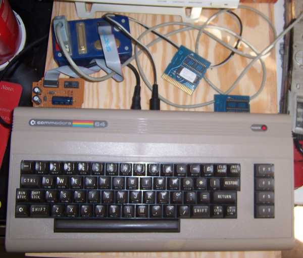
Commodore 64 with RS-232 interface and Game Cartridge Board with EPROM
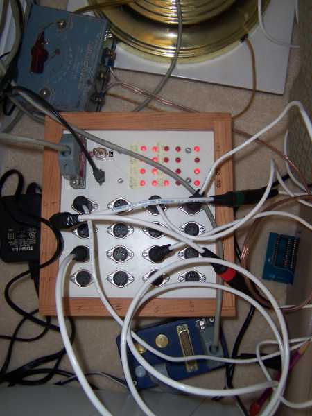
Serial Port Break-out Box - Dec 2007
Serial Port Break-Out Box Circuit
8.3 PC Based Controller
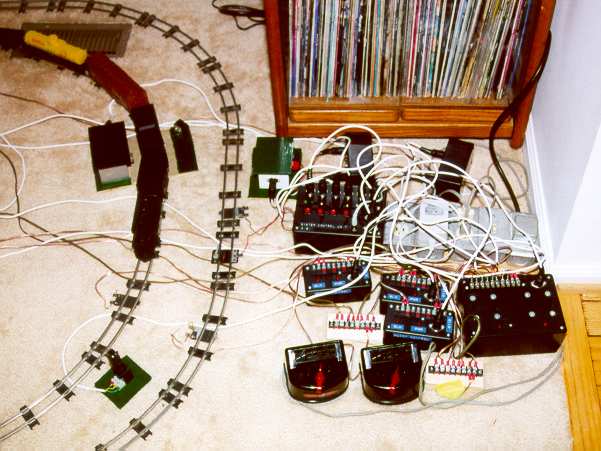
In December 2010 I rewrote the train control software in C for running on a laptop using LINUX as the operating system. I used a USB to Serial Port converter to interface with the Serial Port Break-out box.
PC Train Control Software Code
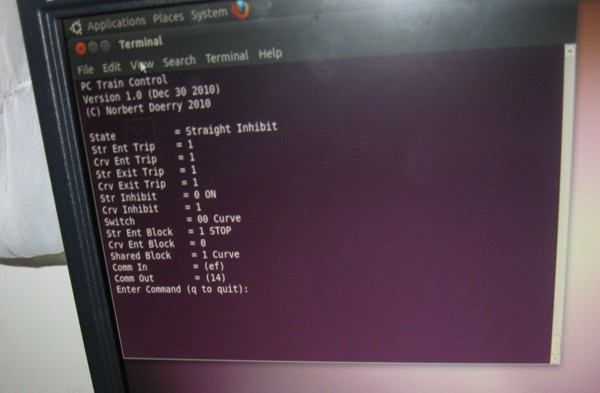
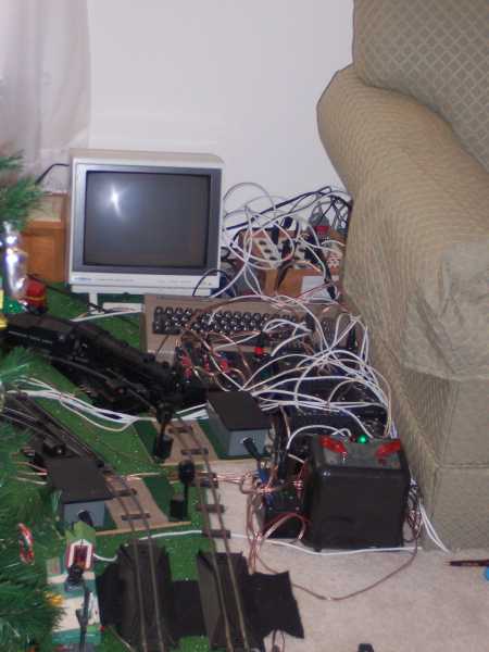
PC Control System (running on LINUX)
8.3 Arduino Based Controller
In 2015 I developed an Arduino based controller for the shared block control for my permnanent layout. The Arduino has a major advantage over a PC in that it boots up in seconds. The Human Machine Interface (HMI) is pretty simple. A three way toggle switch can lock operation for either train, or run in auto. In Auto mode, the first train to reach its control block has access to the shared block while the other train is blocked from entering the shared block. While in automatic mode, a Reset button can force the logic to reset and wait for the next train to enter its control block. The Caboose Block Control Reset will be implemented in the future to block trains should one or more cars inadvertantly decouple -- this hasn't been implemented yet. A two line serial display presents the status of all the inputs and outputs as well as the logic state
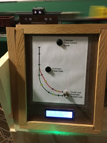
Interface for Arduino Control System for Shared Block Control
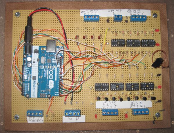
Circuit board for Arduino Control System for Shared Block Control
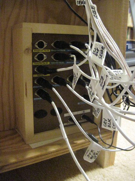
Controller Box for Arduino Control System for Shared Block Control
Circuit and layout for Arduino Based Controller
Software for Arduino Based Controller
9. Emergency Stop
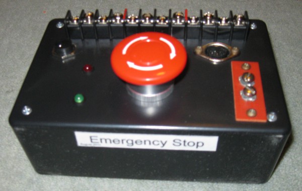
Emergency Stop
This circuit implements an emergency stop for 3 transformers
Emergency Stop Circuit
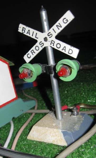
10. Block Signal
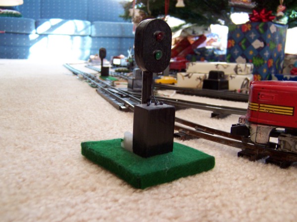
Block Signal
The Master Controller generates signals for a block signal for the entrance of the shared block. Here is a diagram of a block signal I made. The hoods for the lights were made from straws. I hid the resistors for the LEDs in the base block.
Block Signal
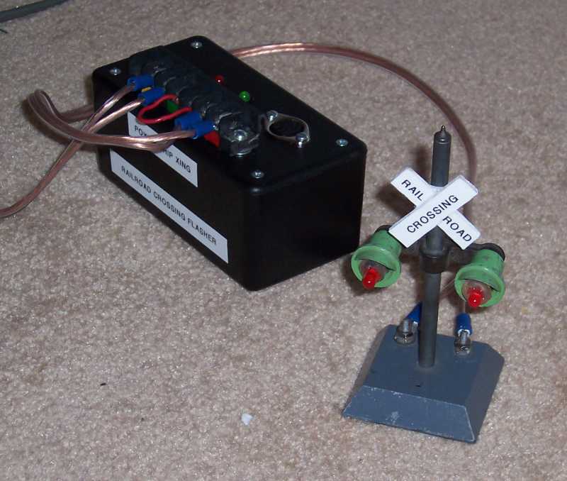
11. Railroasd Crossing Control
 I wanted my crossing signals to flash like the real ones, so I built this circuit. It also allows you to alternately flash two 12V lights for even more realism.
Rail Crossing Flashing Control Circuit
 This circuit alternately flashes both lights on an American Flyer 760 Highway Flasher without having to modify the 760 unit. It does replace the lightbulbs with Light Emitting Diodes.
AF 760 Rail Crossing Alternate Flashing Control Circuit
Yet another AF 760 Rail Crossing Alternate Flashing Control Circuit
AF 760 Rail Crossing Alternate Flashing Control Circuit (a bit newer)
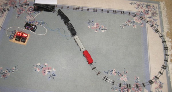
12. Handcar Auto-reversing Control
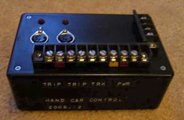
Movie of Auto-Reversing -- Christmas 2006 (Click Picture to View)
This circuit automatically reverses the direction of a handcar that has been converted to DC. It uses two track trips to sense when the handcar should reverse direction and changes the polarity of the power applied to the track.
Hand Car Controller Circuit
13. Remote 120V control
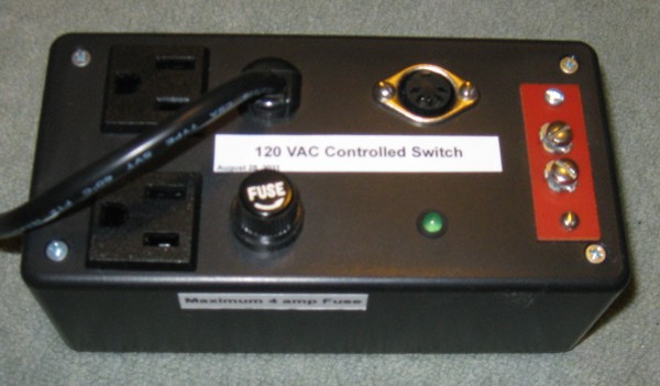
Remote 120V Control
This circuit allows me turn on remote transformers for my accessories when control power is provided by the train control transformers.
Remote 120V Control Circuit Diagram
14. Transformer Considerations
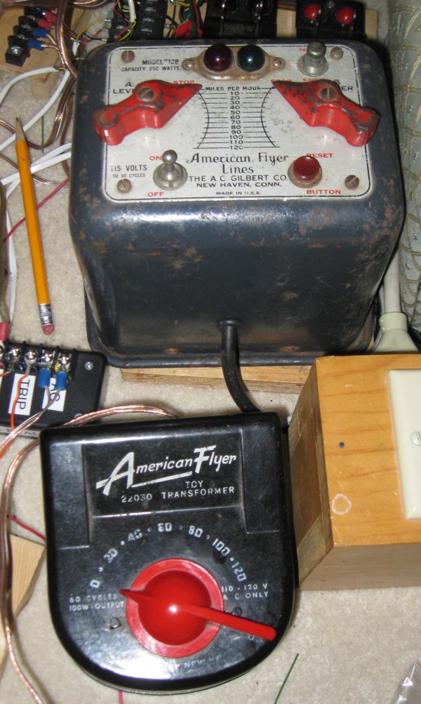
12B (250 Watt) and 22030 (100 Watt) transformers for engine control
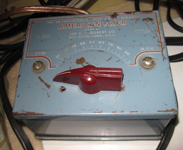
4B (100 Watt) transformer for remote switches
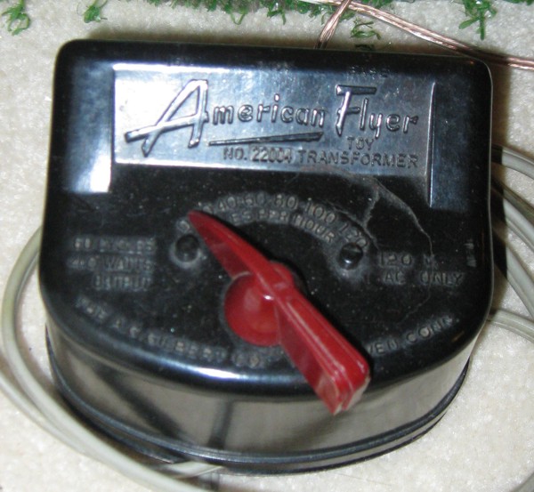
22004(40 Watt) transformer for accessories
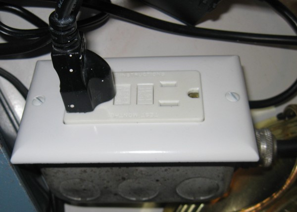
GFCI Outlet for safety
The American Flyer transformers are very robust and work well over 50 years since they were manufactured. That said, one has to be careful when using these old electrical devices. I personally plug the transformers into a GFCI (Ground Fault Current Interrupter) protected outlet. I also inspect the power cords every year and replace any that are cracked. Consider using a 3 prong grounded cord as a replacement cord. Connect the green wire to the metal case or base of the transformer. This will cause your home circuit breaker to trip in the event of an internal short of the hot conductor to the case of the transformer.
I dedicate a number 4 transformer to the remote switches. Operating a remote switch causes a noticable voltage sag, so I prefer to isolate the impact of this on the rest of the system.
I use a 12B, 22030 or a 4B transformer for operating the trains. The 100 - 125 watts per train is sufficient to run the engines, especially if the transformers aren't used for accessories.
For the rest of the accessories, I use a 40 or 50 watt transformer (such as a 22004).
The lower wattage is adequate, and in the case of a short circuit results in a lower short circuit current (and hopefully less damage).
So in a typical layout, I have a total of 4 transformers: 2 for engine control, 1 for switch control, 1 for accessories.
Note that this does not count the 12VDC transformer for the IO Box/Master Controller or the power supply for the Computer.
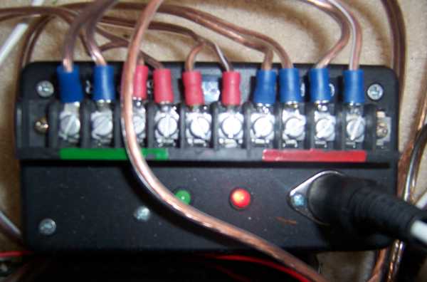
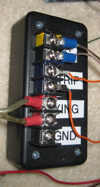
15. Accessory Control Buttons
Accessory Control Button
Since my layouts are tempory, but still soemwhat complex, I've made some effort to improve reliability of the wiring. One thing that really helps is to use terminal strips and wiring with spade terminals. For the accessory buttons, I mounted them onto a piece of wood and wired them to a terminal strip. I've found that a 7 connector terminal strip works great:
2 terminals for power in (Black and Yellow)
2 terminals for daisy-chaining to the next accessory control button (Black and Yellow)
2 terminals for power to the accessory (Black and Yellow)
1 terminal connected to the push button switch. (Green)
NOTE: Black is for the base terminal on the transformer, Yellow for the Accessory Terminal
For some of the control buttons, I included a slide switch to determine whether the Green terminal
connects to the Yellow or the Black terminal through the push button switch. Most accessories need the pushbutton to connect to the Yellow terminal, so I've hard wired a number of accessory buttons in this way.
16. Reverse Loops
Reverse Loop
A reverse loop exists anytime a train can traverse the same stretch of track in opposite directions while travelling forward. As shown in the following figure, reverse loops can cause electrical short circuits if not properly addressed.
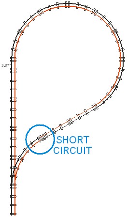
The Electrical Problem due to Reverse Loops
The following block diagram shows the elements of operating with a reverse loop. For AC systems, the normal solution to prevent a short circuit is to use isolation (fiber) pins to isolate a section of track (or at least the outside rails). Either a switch or a relay is used to control the "polarity" of this isolated section of track based on the whether the switch is in the straight or curve position. For fully automatic operation, a switch controller will automatically throw the switch when the train is approaching the switch from within the reverse loop.
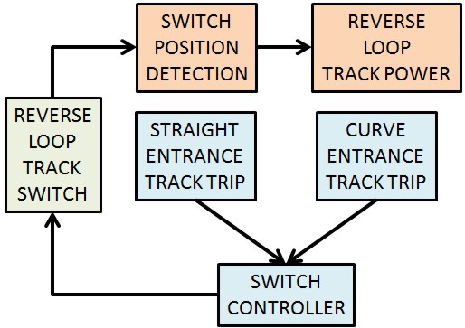
Reverse Loop Control Block Diagram
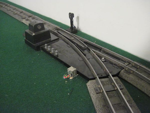
Gilbert made a "No. 695 Reverse Loop Relay" which detected the switch position by using a dual winding latching relay that sensed when the switch coils were energized. This relay also provided the proper "polarity" connection to the outside rails of the reverse loop. The inside rails are controlled by the "2 Train Operation" button on the remote switch. The following picture shows an emulation of this reverse loop relay. It differs from the 695 in that it does not use a latching relay (and therefore on power up may not reflect the proper setting of the switch). It also differs in that it provides the option to completely isolate the reverse loop track and power both rails through this reverse loop relay.
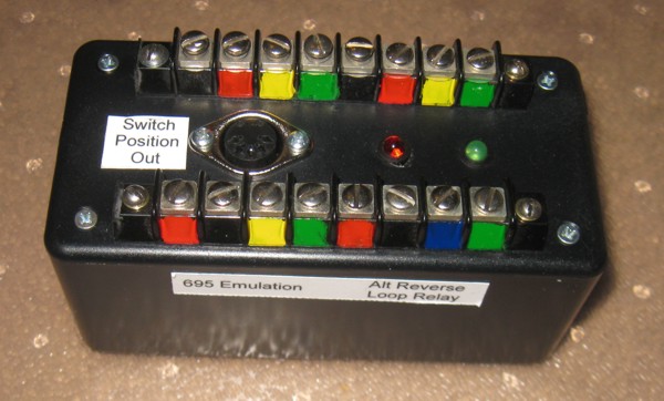
Emulator of No. 695 Reverse Loop Relay
No 695 Reverse Loop Relay Emulation Schematic
Alternate 695 Reverse Loop Relay Emulation
Based on
circuit by Carl Kellenbenz
The previous controllers only changed the polarity of a track section baseed on the last set of switch coils that were energized. The following controller relies on an external switch direction sensor, but in addition to changing polarity of a track section, also changes the position of the switch when the train is fully in the reverse loop.
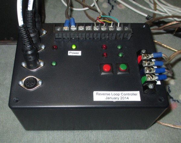
Fully automatic reverse loop controller (click on picture for video)
Schematic for Fully Automatic Reverse Loop Controller
Below is a diagram of the center loop for my permanent layout. An Arduino MEGA is used to control the polarity of each of the eight blocks (F0 through F7) as well as the direction of the switches. The controls determines which block the train is in via a current sensor. The current sensor and block directional control are contained in a single box.
(schematic) A solid state switch controller is used to energize the switches (schematic)
The control interfaces allows the operator to choose how the direction for each switch is established when the train approaches the common end. Options include "no change", "opposite", "random", "always straight", and "always curve." A 2 line serial display shows the current block the train is in, the last block the train is in, the polarity of the current block, the polarity of each of 8 blocks, and whether the current sensor detects a train in the block, the direction of each of the switches, the switch control setting, and which switch coils are energized. Each switch has a switch direction sensor that is used to display the direction of each switch.
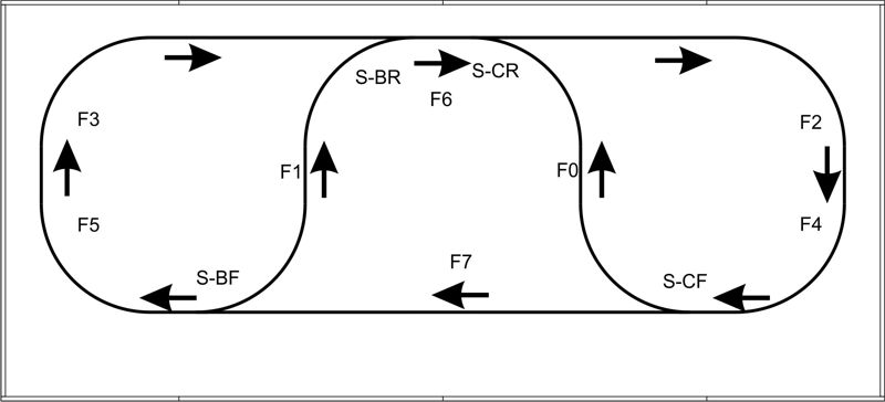
Reverse Loop Track Layout
Here is the control interface ...
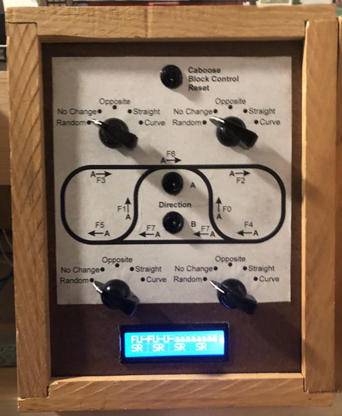
control interface for reverse loop control
Here is the controller under construction ...
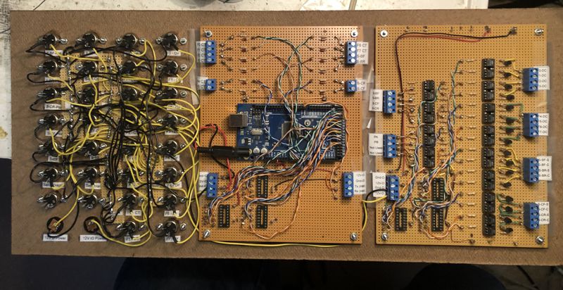
Arduino Mega controller for reverse loop control
Schematic for Arduino Reverse Loop Control
Arduino Mega Software for Reverse Loop Control
100. THINGS I TRIED THAT DIDN'T WORK
100.1 Reed Switch based Current Sensing Track Trip
This trip consists of a Reed Switch that has many turns of wire wrapped around it. You connect the windings in series with the track power of an isolated block. When the engine draws power from the track block, current in the windings generates a magnetic field that closes the contacts. The only problem with A.C. power is that the reed switch actually becomes a buzzer. My experience is that the rapid opening and closing of the
reed switch with even a small sensing current will quickly cause the reed switch to
over heat and the reeds will fuze together.
100.2 Microswitch with roller track trip
Tried to automate the changing of direction of a handcar (converted to DC) by having the handcar brush up alongside a roller microswitch. Unfortunately, it still had enough friction so that the handcar often stuck when it was trying to start in the reverse direction.
Return to Norbert's American Flyer Trains
Return to Norbert's Home Page
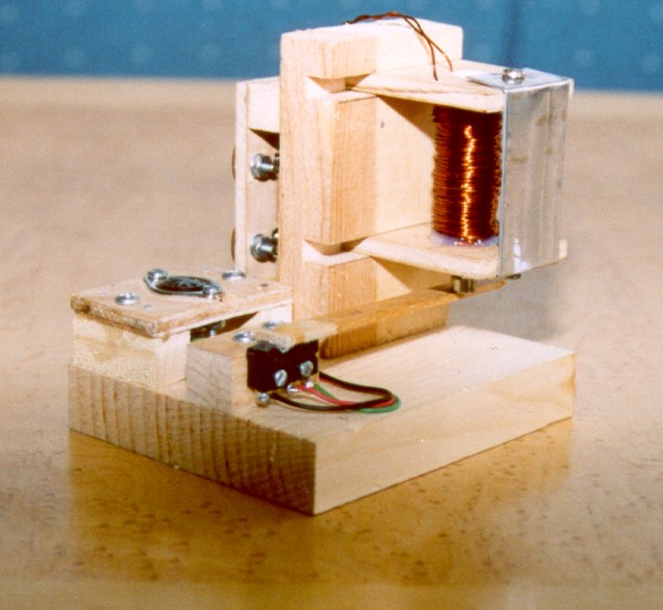 Electric Track Trip